Use Peripherals
This product can be connected to and used with various peripherals, sold separately.
For information on operating, installation, and other procedures, please refer to the manual included with the peripherals.
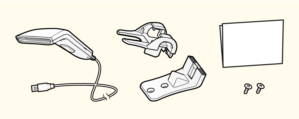
BSH-20U, BSH-20B, BSD-40U, BSH-32U, BSH-32B
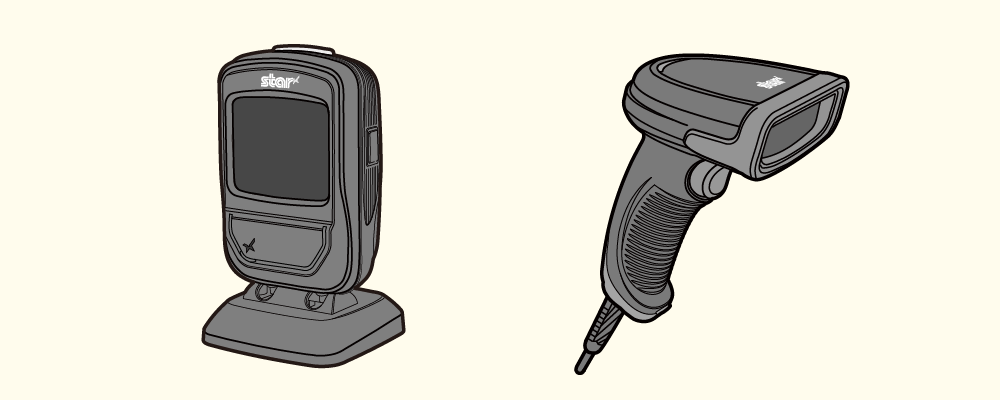
Connect this unit to the USB port of the printer to return the information read by the barcode reader to the host device.
Set Up External Devices (USB port)
Check with each sales company for available purchase models.
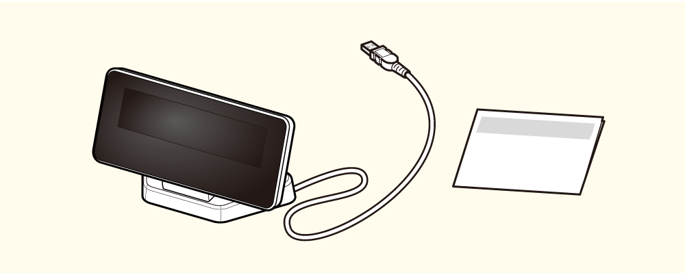
Connect this unit to the USB port of the printer to display various information received from the host device.
Connect this unit to the USB port of the printer to return the information read by the barcode reader to the host device.
Precautions for installing the mC-Sound
Please make sure you follow the procedure "Precautions for installing the melody speaker MCS10" when you connect/ remove Melody Speaker.
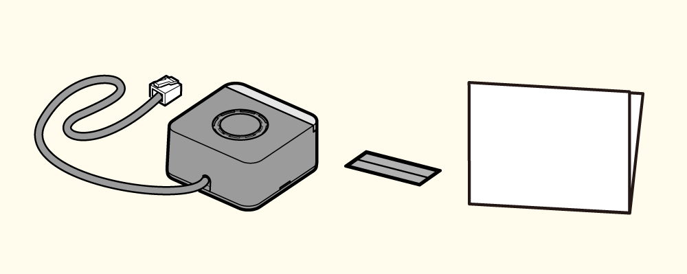
Connect this unit to the external device drive connector on the printer. The melody will sound synchronized with printing.
The settings can be performed in the printer driver and other programs.
If mC-Sound is not recognized even when it is connected to the printer, follow the procedure below and change the printer settings.
- Use an iOS or Android tablet or smartphone to install Star Quick Setup Utility.Use App
- Start Star Quick Setup Utility.
- Connect to the desired printer.
- Tap [Printer Settings], [Memory Switch Settings].
- Set the mode switch at the top to [Bit] and select “Memory Switch 7” from the picker at the bottom, then set “Bit 1” in the Number field to "ON".
- Tap [APPLY].
Set Up External Devices (External device drive connector)
Caution
mC-Sound and Cash Drawer use the same insertion slot (DK port), so they cannot be used together in one printer.
Connect this unit to the external device drive connector. The buzzer will ring in conjunction with printing.
The setting can be performed in the printer driver and other programs.
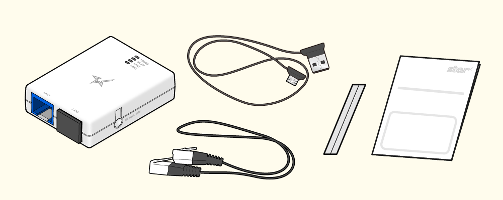
Connect this unit to the LAN port and USB-A port of the printer, connect to a wireless LAN network.
The settings can be performed in the dedicated app.
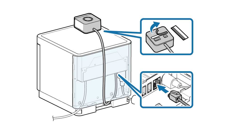
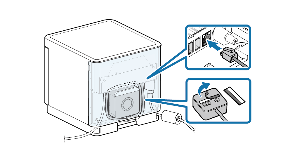
mC-Sound installation procedure
Connect the mC-Sound cable to the external device drive connector on the printer.
Use the installation double-sided tape that was included in the package and apply it at suitable locations.
Before and after connecting the cable to the rear panel, remove and mount the rear cover respectively.
Remove/Mount Rear Cover
Caution
Please turn off a printer and pull out the power plug from the AC outlet and be sure to wait for more than 30 seconds before you connect/remove mC-Sound.
Setting Example
- Installing externally
- Installing internally
Note
- After installation using the installation double-sided tape that was provided with the mC-Sound, the DIP switches of the mC-Sound cannot be changed.
- If this product was installed internally inside a mC-Print3, it will not be possible to use the printer USB port.
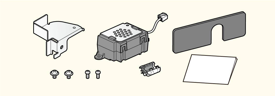
BU01 installation procedure
When installing buzzer BU01 onto the mC-Print3, follow the procedure below.
Before and after connecting the cable to the rear panel, remove and mount the rear cover respectively.
Remove/Mount Rear Cover
Caution
To ensure safety, be sure to turn OFF the power and disconnect the printer power plug from the electric outlet before beginning installation.
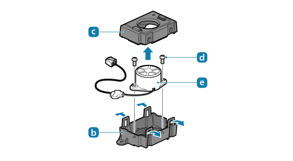
1. Remove the buzzer unit
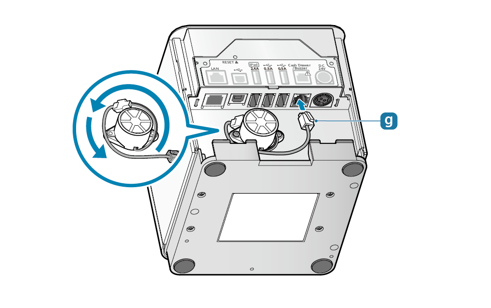
- Remove the ground fitting
 by sliding it in the direction of the arrow.
 - Pull the 4 hooks on the lower case
 outwards, and remove the upper case
 .
.
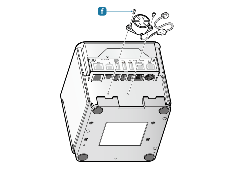
Remove the 2 screws , and remove the buzzer
 from the lower case.

2. Install onto the printer
- Install the buzzer onto the back of the printer.
To install the buzzer, use the two M2.6 screws
 included in the package.
 - Fasten the buzzer securely, then plug the modular jack
 into the external device drive connector on the back of the printer.
 - Installation is completed.
Wire the necessary cables and install the rear cover.